Home >> Products >> Worm Speed Reducer

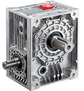
Worm Speed Reducer
A next-generation speed reducer gear
for the modern era
It is possible to use Makishinko worm Speed Reducer in any
conceivable field of power transmission through the technology
and knowledge accumulated in the course of rich experience and
many successes.
The rich variations makes it possible to use worm Speed
Reducer in new fields.
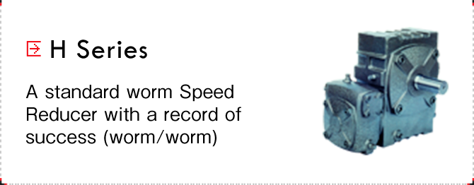
Single speed worm Speed Reducer

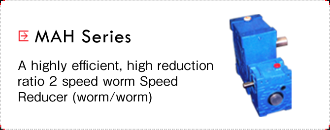
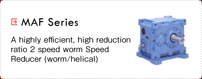
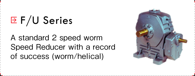
2 speed worm Speed Reducer
Worm/helical Speed Reducer
Worm Speed Reducer features
Principles
A worm gear is a type of interlocking gear composed of a worm shaft and worm wheel. The worm is shaped like a screw and the worm wheel is a type of gear machined to have a tooth profile with the same configuration.
The operation of a worm gear is similar with that of a bolt and nut. The principle is the same as a nut that has been fixed so that it cannot rotate and therefore progresses in the axial direction when the bolt is turned.
The design of a worm gear is thought of through the relationship between the rack and spur gear on the middle plane of the worm wheel.
Structure
Figure 1 The structure of a Worm Speed Reducer
Operation
In a single thread worm, when the worm shaft rotates one time, the worm wheel progresses by one tooth (rotates). In a double thread worm, the wheel progresses by two teeth.
Features
| High reduction ratio | One rotation of the worm rotates the worm wheel by one tooth. Because of this, in a 1 speed Speed Reducer, the wheel can be manufactured so that it will be rotated 1/60 (1/120 in special applications). |
|---|---|
| Orthogonal shaft | The shafts are aligned orthogonally because of the structure. This characteristic makes it possible to layout the turning transmission direction at a right angle. |
| The arbitrariness of the rotation direction | The screw direction of the worm can be clockwise or counterclockwise (generally clockwise). It is possible to change the rotation direction of the worm wheel by changing the screw direction. |
| A wide variety of shaft layouts | The wide variety of shaft layouts is one of the features of interlocking gears.For instance, right shaft output, left shaft output, dual shaft input and dual shaft output, etc., combine for a total of 14 types (Figure 2) and, if attachment orientations are included, it is possible to select from over 40 layouts. |
| Low noise, low vibration | The interlocking of the worm and worm wheel is characteristic because the contact is linear and the relative slide is great. In comparison with rolling power transmission, noise and vibration are extremely low. For this reason, this technology is used to drive medical equipment, elevators and escalators, etc. |
Figure 2 The types of Worm Speed Reducer
The primary specifications of Worm Speed Reducer
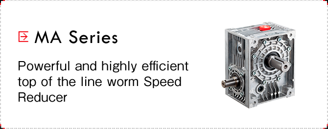
MA Series(Small)
| Center distance(mm) | 32,40 |
|---|---|
| Reduction ratio | 10,20,30,40,50,60 |
| Input capacity(kW) | 0.1~1(at an input of 1800 rpm) |
| Output torque(N・m) | 20~66 |
| Input speed(rpm) | 0~1800 |
MA Series(Medium)
| Center distance(mm) | 50,63,80,100,125,140,160 |
|---|---|
| Reduction ratio | 10,15,20,25,30,40,50,60 |
| Input capacity(kW) | 0.4~30(at an input of 1800 rpm) |
| Output torque(N・m) | 900~3570 |
| Input speed(rpm) | 0~1800 |
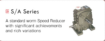
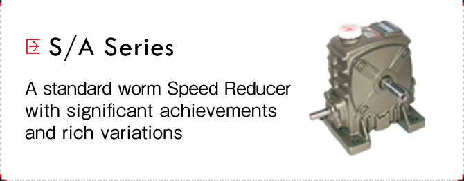
S Series
| Center distance(mm) | 50,60,70,80,100,120,135,155, 175,200,225,250,300,350,400, 450,500 |
|---|---|
| Reduction ratio | 10,15,20,25,30,40,50,60 |
| Input capacity(kW) | 0.3~255(at an input of 1800 rpm) |
| Output torque(N・m) | 50~56600 |
| Input speed(rpm) | 0~1800 |
Key points when selecting a Worm Speed Reducer
Selection
When selecting a Worm Speed Reducer, the procedures for selecting the correct gear are described in the manufacturer catalogs and the series and models should be selected according to those procedures. Particular care should be taken in key areas such as selecting the load index, calculating the overhang load and examining the heat rated capacity from the manufacturer.
Cautions during use
When using a Worm Speed Reducer, the heat produced during the initial period of use is high and running-in operation at 1/4, 1/2 and 3/4 of rated torque for eight hour periods is key to sufficiently achieving the performance of the Worm Speed Reducer.
Maintenance and inspection
After completing running-in operation (approximately 50 hours), it is necessary to change the lubricating oil and to change the lubricating oil after that about 1 time per year according to the operation manual provided by the manufacturer.
Applications and examples of use
Worm Speed Reducer are used widely in a variety of industrial machinery. This includes conveyors, winches, machining equipment, amusement park equipment, stage equipment, multilevel parking garages, automatic assembly equipment, food product manufacturing equipment, medical equipment and traveling cranes.
The example of the use of Worm Speed Reducer in rotary stockers (vertical rotary automated storage), a product of Makishinko, shows the successful utilization of the features of a Worm Speed Reducer including quiet operation in limited space, highly accurate positioning, self-locking, and dual input shafts (an optional manual driveshaft for power outages). Another example is the application of a ball screw in a worm jack.